|
The project comprised the reconstruction and annexation of the treatment plant that already existed within the premises of Chemopetrol Litvínov. The subject matter was formed by the project, supplies, labour and service carried out in connection with the realisation of the construction at all professional levels. These ranged from permission for making alterations and operational documentation to the test implementation itself. Part of it was also the installation of a control system for monitoring and signalling in case of emergency and fault occurrence.
Execution of the project was divided into two parts. The first stage included water utilisation, in particular the treatment of oil-contaminated water, and the second phase attempted to solve the problem of exhaust air filtration. The project had to comply with regulations in accordance with a law on waste gases and guarantee the NEL content in resultant wastewater (100 mg/l NEL). The project was carried out under very complicated conditions of continuous operation without shutting down whilst observing the internal regulations of Chemopetrol, mainly regarding work safety and fire prevention. Finally yet importantly, it was essential to respect the special conditions of work areas where there was a risk of explosion and toxic substances leakage.
The purpose of the construction of the first stage was to address the problem of oil-contaminated wastewater treatment and eliminate all considered potential emergency conditions. The building of the first stage was also executed respecting the uninterrupted operation of the MCHWTP.
In addition, the proposed solution was also based on the current conditions and needs of Chemopetrol a.s. in view of extensive investment activities on the Petrochemie II site. The entire process of air disposal was planned after completion of water utilisation stage 1 following the trial operation and measurement of emissions. When introducing the new technology, the necessity of nitrogen inertisation technology regarding unexpected circumstances cropped up (especially frequent carbohydrate concentration occurrence above the lower explosive limit - LEL). All these difficulties were subsequently incorporated into the planning of the second stage that followed.
Installing the trash screens was an interesting part of the first stage (placed in front of an inlet into the sump pump). The trash screens are fixed in line with the DN 600 chemical wastewater disposal feed system. The wall structure is prefabricated from reinforced concrete used in water management. Automatic self-cleaning trash screen technology has been employed within the duct. The trash screens are equipped with an emergency security overflow (bypass) in order to eliminate reverse water currents in the pipes in case of blockage of the screens. Prior to the construction of the trash screens, a provisional bypass from UPONOR DN 600 drainage pipes was built, with concrete encasing for diverting water during the building process. The bypass length is 21 metres and the bypass longitudinal gradient is 4.29%. The bypass was blocked up at both ends after completion of the first stage.
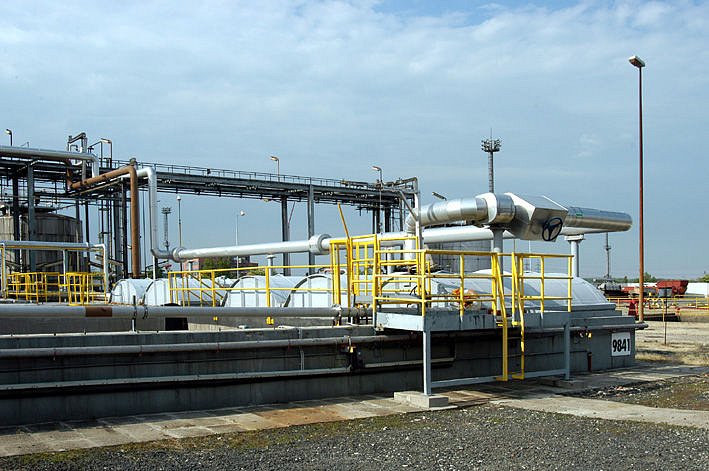
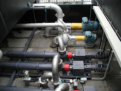
Construction alterations in the sump pump were part and parcel of the reconstruction. The former grit filtering reservoir was converted into a sump pump to catch all incoming wastewater entering the MCHWTP (the reservoir also separates off powerful currents). The reservoir is covered with a hard stainless steel lid with sealed passages for pump suction. The lid is anchored into the existing surrounding reinforced concrete frame of the grit filter. The horizontal stainless steel structure was fitted at the mounting point of 243.55 (for placing pumps). Beneath the heaviest SULZER rainwater pump is a strut beam anchored into sloping concrete. A groove was cut into the gradient of the concrete for the suction pump pipework, the shape of which results from the real location of pumps. Existing openings of the safety overflow and inlet on the trash screen are sealed with concrete. In order to fix the pipes it was necessary to cut out openings for pressure outlet pipework and for a new safety overflow leading into a retention tank. The steel structure of a crane track serves for the disassembling of pumps, a 1-ton crane crab can be hung on the profile.
Other features of the first stage were mechanical pre-treatment (integrated IHP 100 pre-cleaning devices of the above ground type), two independent lamella settlers, oil separator, cesspools, retention tank modifiers and a reservoir for treated water and chemical treatment dosing. At the same time, the main control centre was altered to fulfil the needs of newly developed technology and control methods. Ahead of schedule, a nitrogen pipe connection was added within this stage with technological elements for the inertisation of spaces with ceilings in the MCHWTP.
Within the scope of the second stage, the existing idle spaces of the MCHWTP were sandblasted and cleaned. This concerned underground rooms of a former trash screen, TPI oil separators and retention tanks beneath the helical rainwater pumps. After cleaning, these rooms were sealed off and refurbished. For the needs of a combustion unit (CU), it was necessary to join a connecting pipe of the industrial water supply, compressed air and natural gas. Furthermore, existing rooms in the operational building were altered for the placement of JUM analysers and for technical gases storage. In addition, alterations in the distribution centre were made in order to fix more distributors. The only landscaping work was related to excavations for the foundation slab of the CU. The hardened concrete surface for supporting the CU lies on a gravel base between building 9851 (the main control centre) and a pipe bridge, no.172. The area had been localised with regard to fire and safety precautions and to avoid existing utility lines. Commencement of testing for the quality and quantity of exhaust air from covered reservoirs using MCHWTP’s technology began after thorough trials of the water utilisation section had started. The mass of air contains a considerable amount of free carbohydrates. Detekta s.r.o. –, the authorised laboratory for emission and pollution control from May 2003 to August 2003, was charged with the gauging of it. Conclusions and results derived from their measurements were used as the basis for a solution proposal for the second stage of exhaust air treatment (half-operational detection of the volume and composition of air masses). On the basis of this data, the resultant method of exhaust gas combustion technology was selected and then sourced from EVECO Brno s.r.o.
Located on the open space next to building no.9851, the emission combustion unit is designed for unmanned and continuous operation. Exhaust gases, retracted from the MCHWTP, are led via a DN300 manifold through a safety valve and a valve for switching operation modes for the suction technology governing exhaust gas combustion. Prior to entering the unit, two independent tests of the continual detection of gas concentration and exhalation of flammable liquids are conducted as the regulation (regular operation) and safety element (inertisation). Two JUM analysers have their test lines placed on the outlet collecting pipe of the DN 300 air mass exhaust in front of the combustion unit. The JUM analysers including the sample modifiers are located in the analyser room. In the input H201 sump pump, two extraction test lines for measuring intake into the MCHWTP were employed by the gauge sampling flammable gases and exhalations. The device controls preset levels of concentrations in % LEL. The Polytron IR sensors with sample modifiers are located directly beside the H201 reservoir; their sampling pumps are in the new analyser room, where also the JUM analysers are situated.
The technology of the combustion unit is controlled in accordance with the analysers fixed on the inlet pipe for exhaust air into the exhaust gas combustion equipment in relation to the real amount of carbohydrates from MCHWTP’s entire machinery. On the other hand, the sensors fixed in the H201 sump pump serve for pre-alarm warnings and for activating the nitrogen inertisation process. Nitrogen inertisation is regulated by gauging the oxygen volume in the exhausted air. If the volume of oxygen were to drop to less than 7% of the O2 content, then by means of a regulative device on the nitrogen supply it would result in keeping a permanent level of the ratio of oxygen and nitrogen in the covered equipment.
The main control unit secures the regulation and safety of the entire incinerator. The distributor is in the main control centre of the MCHWTP next to the incinerator. Necessary field instrumentation accompanies the device. The system of control is formed by a programmable control system. The distributor of the combustion unit’s control system is in the main control centre.
The whole system works fully automatically and does not require permanent attendance. Beyond the safety of the system, the equipment is secured by the dual monitoring of concentrations of organic vapour in the pump station.
|